Introduction
This project designs and implements a complete network infrastructure for a fictional company, ASI ltd., built entirely in GNS3 with Cisco IOS routers. ASI operates four locations: three branch offices in Ljubuški, Grude, and Čapljina, plus a data center in Zagreb. The goal was a network that connects all sites, provides internet access everywhere, and tolerates failures of individual links or entire segments.
The lab covers the full stack of everyday network services — DHCP, NAT/PAT — through to advanced technologies: MPLS L3 VPN as the primary path between branches, GRE tunnels protected by IPsec as the backup path, and HSRP with IP SLA tracking for internet redundancy at the data center.
Particular emphasis was placed on resilience. A multi-tier failover mechanism keeps the network functional even when individual links or whole segments fail, with a strictly defined priority order: MPLS first, GRE+IPsec second, and a dedicated backup link as the last resort.
Beyond the base build, the project includes three live migration scenarios performed against a running network: moving the PE-CE routing protocol from EIGRP to OSPF, moving the DC overlay tunnels from static routing to EIGRP, and finally migrating the site-to-site IPsec tunnels to a DMVPN Dual-Hub Dual-Cloud Phase 3 design.
Network Topology and Addressing Plan
Topology Segments
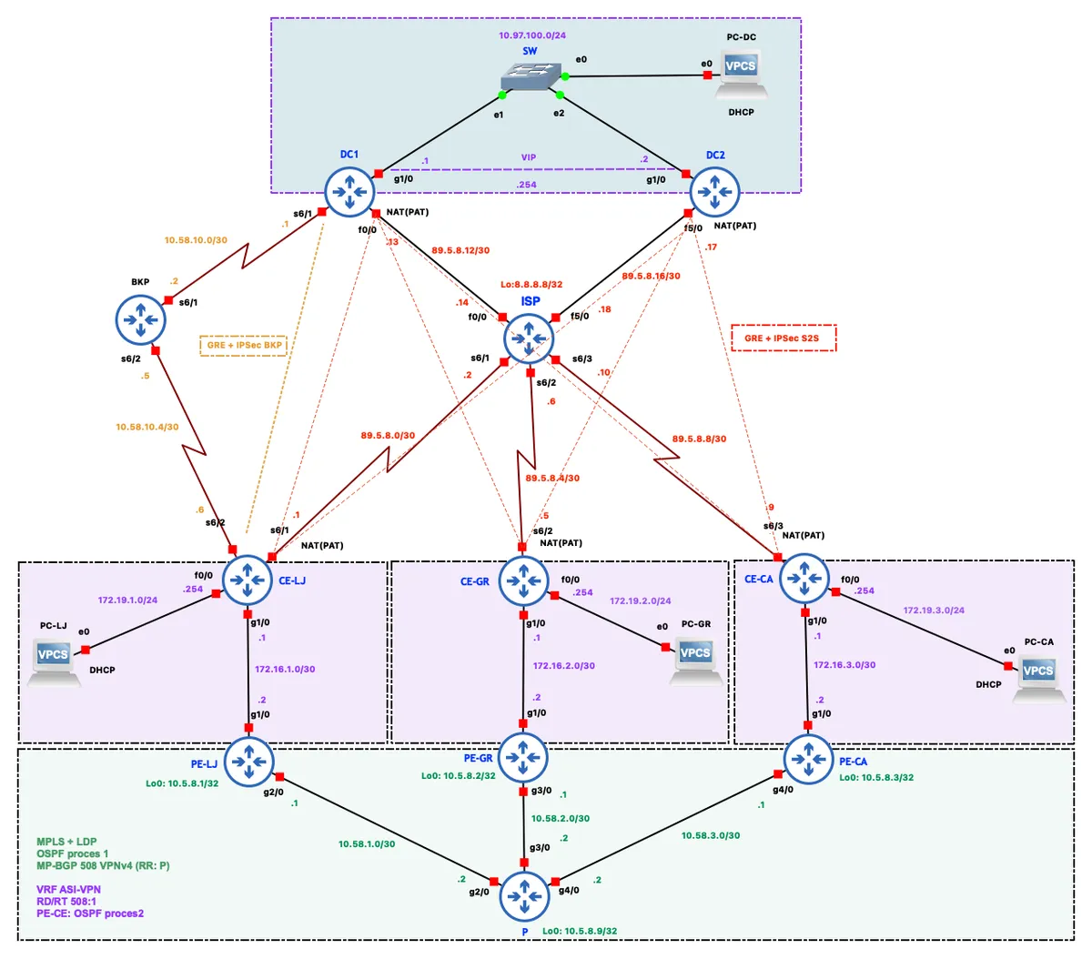
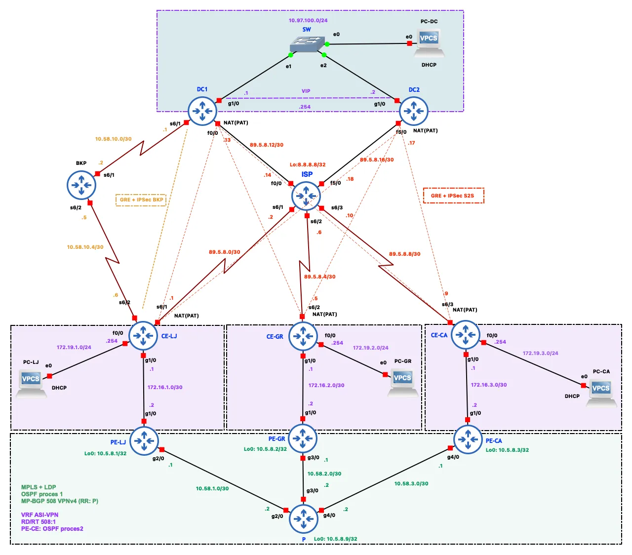
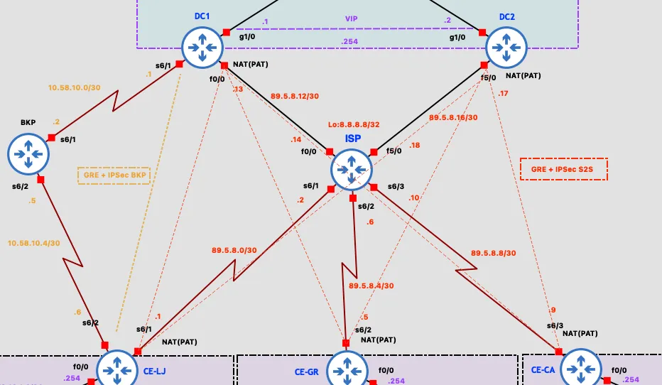
The topology splits into three logical segments connected via the ISP and an MPLS provider network.
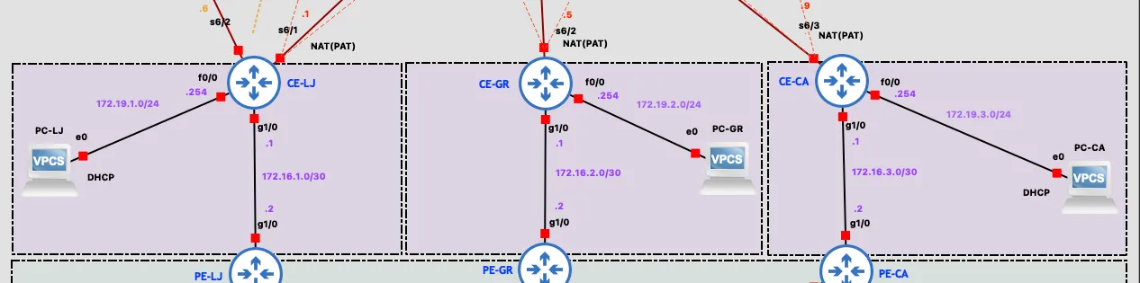
The customer segment consists of the three branch sites. Each has a CE (Customer Edge) router that acts as the LAN default gateway and DHCP server. On the WAN side, every CE has three connections: a serial link to the ISP for internet access, a GigabitEthernet link to its PE router for MPLS, and GRE+IPsec tunnels over the internet to the data center. CE-LJ additionally has a serial link to a dedicated BKP router, used as the last-resort path to the data center.
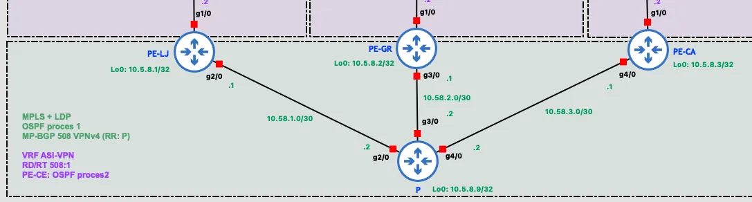
The provider segment (MPLS core) consists of three PE (Provider Edge) routers (PE-LJ, PE-GR, PE-CA) and a single P (Provider) router in a star topology, with P at the center. This segment runs OSPF, MPLS with LDP for label switching, and MP-BGP with the VPNv4 address-family for exchanging VPN routes. The P router also acts as a BGP route reflector, avoiding the need for a full mesh of BGP sessions between the PE routers.
The data center, located in Zagreb, consists of two routers — DC1 (primary gateway) and DC2 (backup gateway) — connected to a shared LAN segment (10.97.100.0/24) through a switch. DC1 and DC2 run HSRP with a virtual IP of 10.97.100.254 as the gateway for devices on the DC LAN. Both DC routers have their own internet links via the ISP, plus GRE+IPsec tunnels to every branch. DC1 additionally has a serial link to the BKP router for the total-internet-outage scenario.
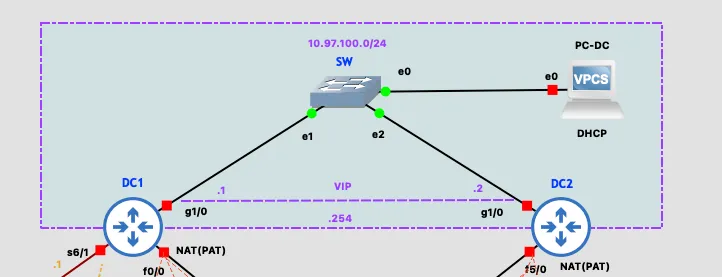
The ISP router simulates an internet service provider, connected to all CE routers and both DC routers via serial links. Its Loopback0 address, 8.8.8.8/32, simulates a public DNS server used for connectivity testing. The BKP router acts purely as a relay between CE-LJ and DC1 for the scenario where CE-LJ loses both its ISP and MPLS links.
Addressing Scheme
- Branch LAN subnets:
172.19.X.0/24 - Public WAN space:
89.5.8.0/24 - MPLS core links:
10.58.X.0/30 - MPLS loopbacks:
10.5.8.X/32 - DC LAN:
10.97.100.0/24 - BGP ASN:
508 - EIGRP AS:
197 - VRF Route Distinguisher / Route Target:
508:1— BGP ASN + VPN sequence number - GRE tunnel addresses:
10.10.X0.0/30for tunnels to DC1,10.10.(X0+10).0/30for tunnels to DC2, whereXis the branch number
The resulting per-site LAN addressing:
| Location | Subnet | Gateway | DHCP range |
|---|---|---|---|
| Ljubuški (LJ) | 172.19.1.0/24 | 172.19.1.254 | .1–.239 |
| Grude (GR) | 172.19.2.0/24 | 172.19.2.254 | .1–.239 |
| Čapljina (CA) | 172.19.3.0/24 | 172.19.3.254 | .1–.239 |
| DC – Zagreb | 10.97.100.0/24 | 10.97.100.254 (VIP) | static |
Core Network Services
DHCP
Every CE router runs a DHCP server for its LAN, so client devices receive their network configuration automatically. Example from CE-LJ:
ip dhcp excluded-address 172.19.1.240 172.19.1.255ip dhcp pool LAN-LJ network 172.19.1.0 255.255.255.0 default-router 172.19.1.254 dns-server 8.8.8.8The ip dhcp excluded-address command reserves the top of the range (.240–.255) for network equipment — most importantly the default gateway address (.254) — preventing an address collision if the server were to hand it out to a client. The network statement defines the pool, so clients receive addresses .1–.239. default-router points clients at the CE’s FastEthernet0/0 interface as their gateway, and dns-server points them at 8.8.8.8, which conveniently is also the ISP router’s Loopback0 — doubling as both a DNS resolver and an internet-reachability test target.
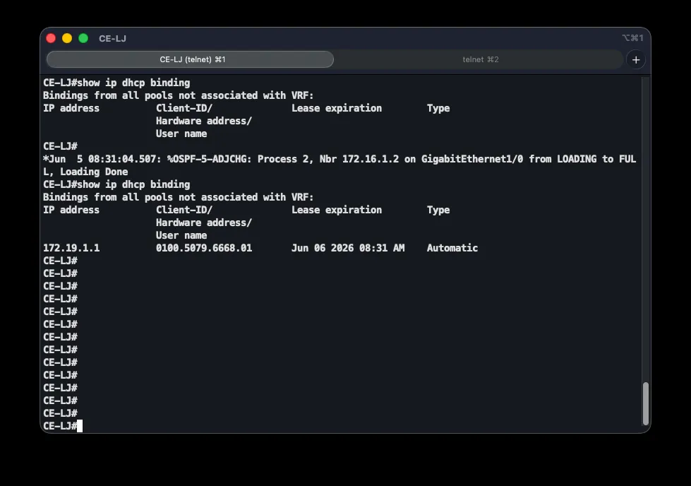
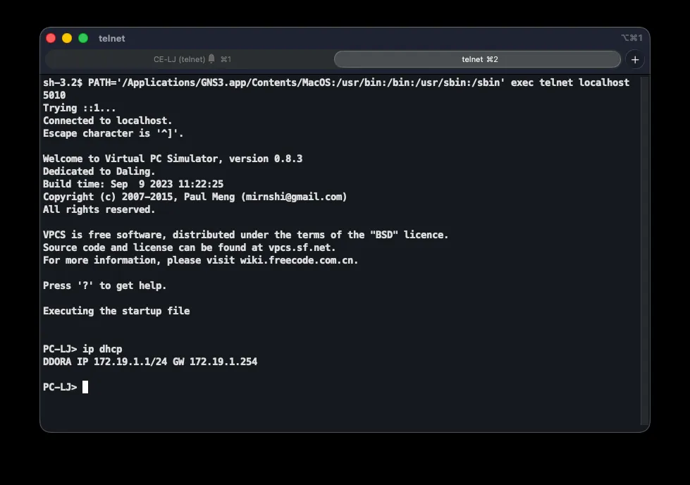
Correct operation is verified on a client PC with ip dhcp, and on the CE router with show ip dhcp binding, which lists assigned addresses alongside their client MAC addresses.
NAT and Internet Access
Since branch LANs use private addressing that isn’t routable on the public internet, every CE router runs NAT in PAT (overload) mode, so all devices in a branch share a single public IP on the WAN interface. Example from CE-LJ:
interface FastEthernet0/0 ip nat insideinterface Serial6/1 ip nat outside!ip nat inside source list 1 interface Serial6/1 overloadaccess-list 1 permit 172.19.1.0 0.0.0.255!ip route 0.0.0.0 0.0.0.0 89.5.8.2The LAN-facing interface is marked inside and the ISP-facing interface outside, defining the translation direction. The key command, ip nat inside source list 1 interface Serial6/1 overload, translates source addresses matching access list 1 to the WAN interface address (89.5.8.1); overload lets many devices share that single public address by differentiating on port numbers. The default route sends all unmatched traffic to the ISP.
| Branch | Inside (LAN) | Outside (WAN) | Public IP | Next-hop (ISP) |
|---|---|---|---|---|
| Ljubuški | Fa0/0 | Se6/1 | 89.5.8.1 | 89.5.8.2 |
| Grude | Fa0/0 | Se6/2 | 89.5.8.5 | 89.5.8.6 |
| Čapljina | Fa0/0 | Se6/3 | 89.5.8.9 | 89.5.8.10 |
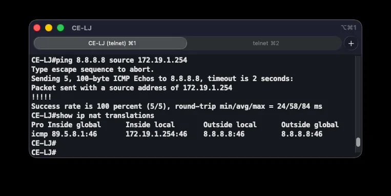
NAT is verified with ping 8.8.8.8 source 172.19.1.254 on the CE router (forcing the LAN address as the source to trigger translation), and ping 8.8.8.8 from a client to exercise the whole chain. show ip nat translations shows active source-address/port to translated-address/port mappings.
MPLS L3 VPN
Primary inter-branch communication runs over MPLS L3 VPN, letting all three branches exchange traffic across the provider network using private addressing — without the provider (P) router ever needing to know the customer’s address space. The design is built in four layers, each depending on the one below it.
OSPF Underlay
The first layer is OSPF, providing reachability between all core routers via their loopback addresses — the foundation that both label exchange and BGP sessions depend on:
router ospf 1 router-id 10.5.8.9 network 10.5.8.9 0.0.0.0 area 0 network 10.58.1.0 0.0.0.3 area 0 network 10.58.2.0 0.0.0.3 area 0 network 10.58.3.0 0.0.0.3 area 0A single area (area 0) is used since the topology is a simple star centered on the P router. Only core links and loopbacks are advertised — PE-CE links belong to the customer’s VRF and are excluded. The router ID is explicitly pinned to the loopback address for stability.
MPLS and LDP
The second layer adds label switching and LDP for exchanging labels between routers. Every core interface gets mpls ip, and the LDP identity is tied to the loopback:
interface GigabitEthernet2/0 mpls ip!mpls ldp router-id Loopback0 forceWith MPLS enabled, core routers forward packets based on a label instead of inspecting the full IP header — faster, and more importantly, it isolates VPN traffic so the P router never needs to learn customer prefixes. The force keyword makes LDP use the loopback address immediately, since that interface never goes down.
MP-BGP VPNv4
The third layer is MP-BGP with the VPNv4 address-family, carrying VPN routes between PE routers. The P router acts as a route reflector, eliminating the need for a full mesh of BGP sessions. Configuration on P and on a representative PE:
router bgp 508 no bgp default ipv4-unicast neighbor 10.5.8.1 remote-as 508 neighbor 10.5.8.1 update-source Loopback0 address-family vpnv4 neighbor 10.5.8.1 activate neighbor 10.5.8.1 route-reflector-client!router bgp 508 no bgp default ipv4-unicast neighbor 10.5.8.9 remote-as 508 neighbor 10.5.8.9 update-source Loopback0 address-family vpnv4 neighbor 10.5.8.9 activate neighbor 10.5.8.9 send-community both address-family ipv4 vrf ASI-VPN redistribute eigrp 197no bgp default ipv4-unicast disables plain IPv4 BGP since only VPNv4 is used. Sessions ride over loopback addresses (update-source Loopback0), reachable from any direction thanks to OSPF. Marking P as route-reflector-client cuts the required sessions from six to three. send-community both propagates the extended community attributes carrying the Route Target, and redistribute eigrp 197 injects routes learned from the CE routers into BGP so other PEs can learn them. The autonomous system number 508 comes from the addressing scheme above.
VRF and EIGRP on the PE-CE Segment
The fourth layer introduces a VRF (Virtual Routing and Forwarding) instance on each PE router, with EIGRP as the PE-CE routing protocol:
ip vrf ASI-VPN rd 508:1 route-target export 508:1 route-target import 508:1!interface GigabitEthernet1/0 ip vrf forwarding ASI-VPN ip address 172.16.1.2 255.255.255.252!router eigrp 197 address-family ipv4 vrf ASI-VPN network 172.16.1.0 0.0.0.3 redistribute bgp 508 metric 1500 100 255 1 1500 autonomous-system 197 no auto-summary!router eigrp 197 network 172.19.1.0 0.0.0.255 network 172.16.1.0 0.0.0.3 no auto-summaryThe VRF gives the ASI customer its own routing table, kept separate from the provider’s and from any other customer’s. The Route Distinguisher (rd 508:1) makes routes globally unique, while the Route Target (route-target export/import 508:1) controls which routes the VRF exports to and imports from BGP — since every PE uses the same RT, all branches exchange routes with each other. Note that ip vrf forwarding clears any IP address previously set on the interface, so it must be reconfigured afterward. redistribute bgp 508 with an explicit metric carries routes from other branches out of BGP into EIGRP, since BGP itself carries no EIGRP metric. The EIGRP AS number 197 is also derived from the addressing scheme.
Packet Flow and Verification
When a host in Ljubuški talks to a host in Grude, the packet first reaches CE-LJ, which forwards it to PE-LJ over its EIGRP route. PE-LJ’s VRF table and BGP determine the destination sits behind PE-GR and push two MPLS labels onto the packet — an outer label for transport to PE-GR and an inner label identifying the VPN. The P router inspects only the outer label, swaps it, and forwards. PE-GR pops both labels and, using its VRF table and EIGRP, forwards the packet to CE-GR and finally to the destination host.
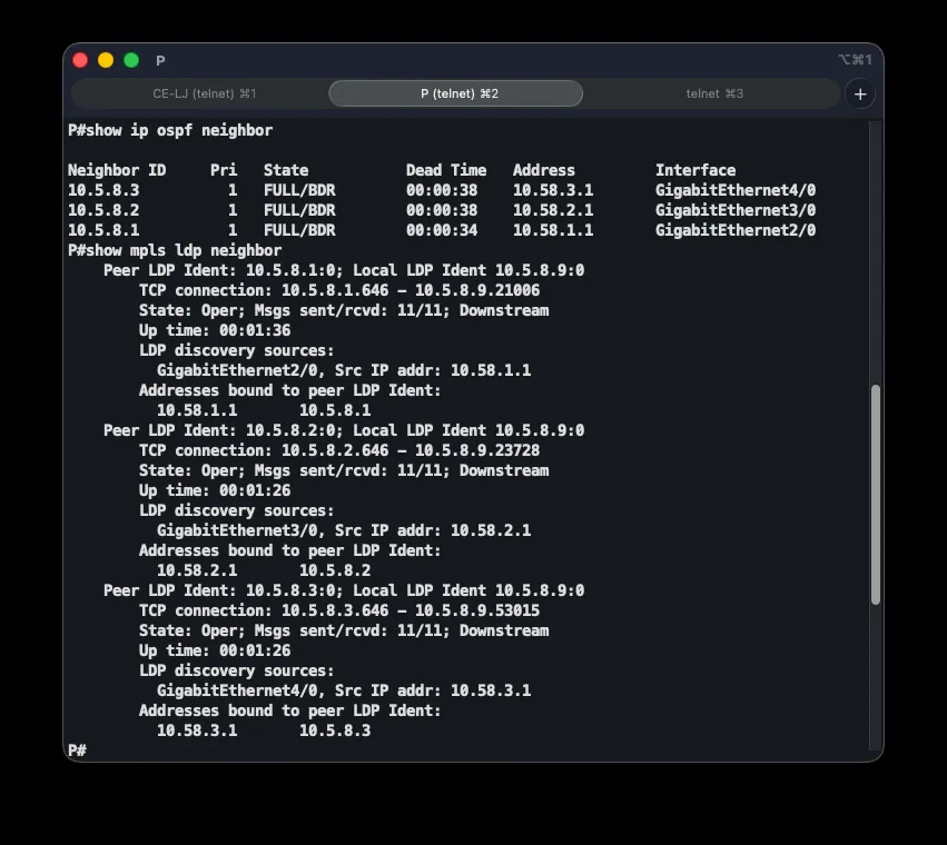
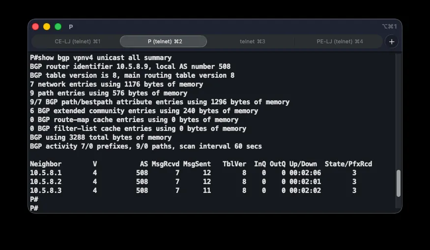
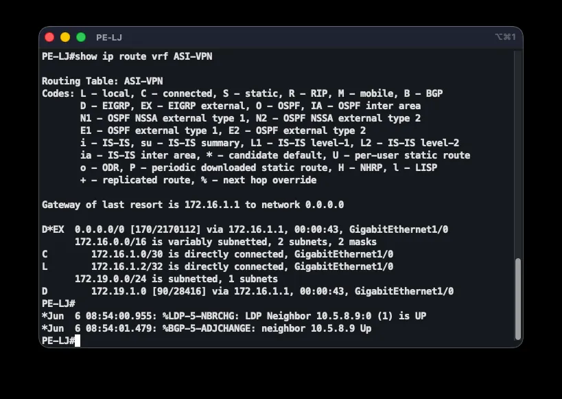
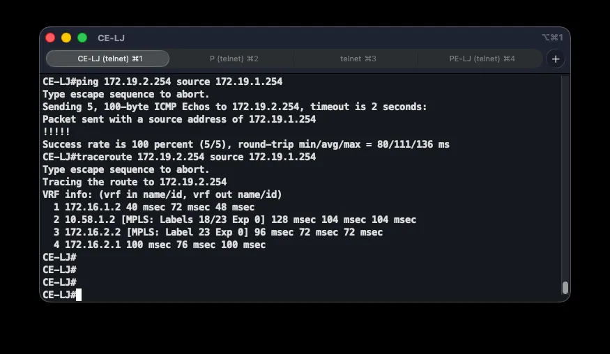
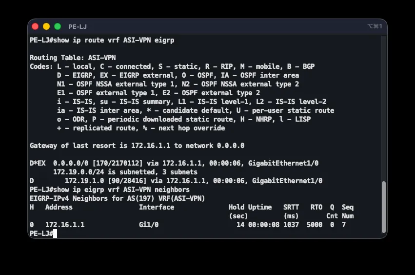
End-to-end correctness is checked with a chain of commands: show ip ospf neighbor on P should show three FULL neighbors; show mpls ldp neighbor three Oper LDP neighbors; show bgp vpnv4 unicast all summary three BGP neighbors with received prefixes; and show ip route vrf ASI-VPN on a PE router shows B (BGP) and D (EIGRP) routes for every branch. Connectivity is confirmed with ping 172.19.2.254 source 172.19.1.254, and traceroute reveals the path through the MPLS core along with the labels in use.
GRE Tunnels Protected by IPsec
As a backup path for an MPLS outage, GRE tunnels over the internet, protected by IPsec, connect every branch to both data center routers. Each branch has two tunnels — one to DC1 as the primary hub, one to DC2 as the backup hub.
| Tunnel | Source | Destination | Subnet |
|---|---|---|---|
| Tunnel10 | CE-LJ (89.5.8.1) | DC1 (89.5.8.13) | 10.10.10.0/30 |
| Tunnel20 | CE-GR (89.5.8.5) | DC1 (89.5.8.13) | 10.10.20.0/30 |
| Tunnel30 | CE-CA (89.5.8.9) | DC1 (89.5.8.13) | 10.10.30.0/30 |
| Tunnel40 | CE-LJ (89.5.8.1) | DC2 (89.5.8.17) | 10.10.40.0/30 |
| Tunnel50 | CE-GR (89.5.8.5) | DC2 (89.5.8.17) | 10.10.50.0/30 |
| Tunnel60 | CE-CA (89.5.8.9) | DC2 (89.5.8.17) | 10.10.60.0/30 |
The GRE side, on CE-LJ towards DC1:
interface Tunnel10 description GRE to DC1 ip address 10.10.10.2 255.255.255.252 tunnel source Serial6/1 tunnel destination 89.5.8.13 tunnel protection ipsec profile ASI-IPSECGRE encapsulates traffic in a new IP packet to create a virtual tunnel across the internet, but provides no confidentiality on its own — the ISP sees only the outer IP header. tunnel protection ipsec profile ASI-IPSEC automatically encrypts everything that traverses the tunnel. The IPsec configuration in two phases:
crypto isakmp policy 10 encryption aes 256 hash sha256 authentication pre-share group 14 lifetime 86400!crypto isakmp key ASI-VPN-KEY address 0.0.0.0 0.0.0.0!crypto ipsec transform-set ASI-TS esp-aes 256 esp-sha256-hmac mode transport!crypto ipsec profile ASI-IPSEC set transform-set ASI-TSThe ISAKMP policy (Phase 1) negotiates AES-256 encryption, SHA-256 integrity, pre-shared key authentication, and Diffie-Hellman group 14 (2048-bit), renegotiated every 24 hours. The transform-set (Phase 2) protects the actual traffic with ESP using AES-256 and SHA-256. Transport mode is used rather than tunnel mode — more efficient in combination with GRE, since GRE already adds its own header. The IPsec profile ties the transform-set to the tunnel interface; this tunnel protection approach is cleaner and more modern than classic crypto maps.
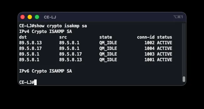
Tunnel health is checked with show crypto isakmp sa — a QM_IDLE state confirms a successful Phase 1 session — and show crypto ipsec sa, whose encrypt/decrypt packet counters confirm traffic is genuinely being encrypted.
Internet-Facing Access Lists
To protect the network from unsolicited access from the internet, every router with an internet-facing interface runs an extended access list named INTERNET-IN, applied inbound. Example from CE-LJ:
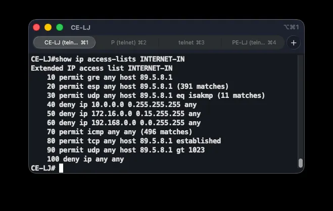
ip access-list extended INTERNET-IN permit gre any host 89.5.8.1 permit esp any host 89.5.8.1 permit udp any host 89.5.8.1 eq 500 deny ip 10.0.0.0 0.255.255.255 any deny ip 172.16.0.0 0.15.255.255 any deny ip 192.168.0.0 0.0.255.255 any permit icmp any any permit tcp any host 89.5.8.1 established permit udp any host 89.5.8.1 gt 1023 deny ip any any!interface Serial6/1 ip access-group INTERNET-IN inThe first group of rules permits the protocols required for the VPN tunnels: GRE (protocol 47), ESP (protocol 50, carrying encrypted payload), and ISAKMP on UDP port 500 for key exchange. Next come anti-spoofing rules that drop inbound packets claiming RFC 1918 private source addresses — such addresses have no legitimate business arriving from the public internet. permit icmp any any allows diagnostics. Two rules handle return traffic: permit tcp ... established allows only packets belonging to already-established TCP sessions, and permit udp ... gt 1023 allows UDP responses on the high ports used by PAT — these two rules exist only on the branch routers, since the DC routers don’t perform NAT. The explicit trailing deny ip any any, while implicit by default, is added for visibility into per-rule hit counts.
The DC routers run the same list, minus the NAT-return rules, adjusted for their own public addresses (89.5.8.13 for DC1, 89.5.8.17 for DC2).
The list is verified with show ip access-lists INTERNET-IN, which shows hit counts per rule, confirming traffic actually matches the expected entries — alongside checks that internet access and MPLS/GRE connectivity still work after applying it.
Redundancy and Failover Mechanisms
Beyond basic connectivity, network resilience was a core requirement. Three redundancy mechanisms work together to keep the network running through link or segment failures: automatic failover of inter-branch traffic from MPLS to GRE+IPsec, internet redundancy at the data center via HSRP and IP SLA, and a multi-tier failover for branch internet access.
Branch-to-Branch Failover: MPLS to GRE+IPsec
The primary inter-branch path is MPLS L3 VPN. If it fails, traffic automatically shifts to the GRE+IPsec tunnels from the previous section. The mechanism relies on floating static routes with deliberately raised administrative distances (AD), so they only take effect once the better path disappears.
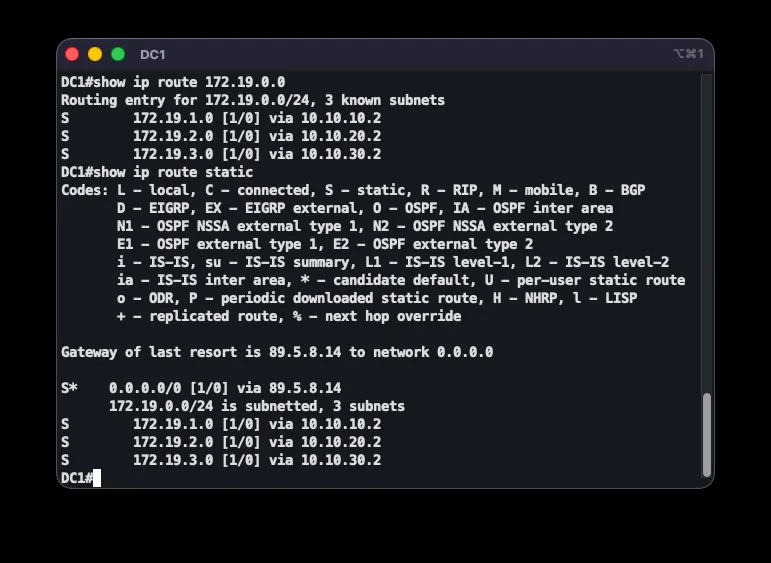
Configuration on CE-LJ:
ip route 172.19.2.0 255.255.255.0 10.10.10.1 200ip route 172.19.3.0 255.255.255.0 10.10.10.1 200ip route 10.97.100.0 255.255.255.0 10.10.10.1 200ip route 172.19.2.0 255.255.255.0 10.10.40.1 210ip route 172.19.3.0 255.255.255.0 10.10.40.1 210ip route 10.97.100.0 255.255.255.0 10.10.40.1 210A normal static route has AD 1, but here the routes use AD 200 (via the tunnel to DC1) and AD 210 (via the tunnel to DC2). Since EIGRP over MPLS has AD 90, it always wins while available. Only once MPLS fails and the EIGRP neighbor is lost does the AD-90 route disappear, letting the AD-200 floating route through the DC1 tunnel take over. If that path is also unavailable, the AD-210 route via DC2 activates. This establishes a strict failover order:
- Priority 1 — MPLS (EIGRP, AD 90): PE link active, EIGRP neighbor established.
- Priority 2 — GRE via DC1 (AD 200): MPLS down, tunnel to DC1 active.
- Priority 3 — GRE via DC2 (AD 210): MPLS and DC1 tunnel both down, tunnel to DC2 active.
The DC routers, which don’t participate in MPLS, run plain static routes to the branches through the corresponding tunnels.
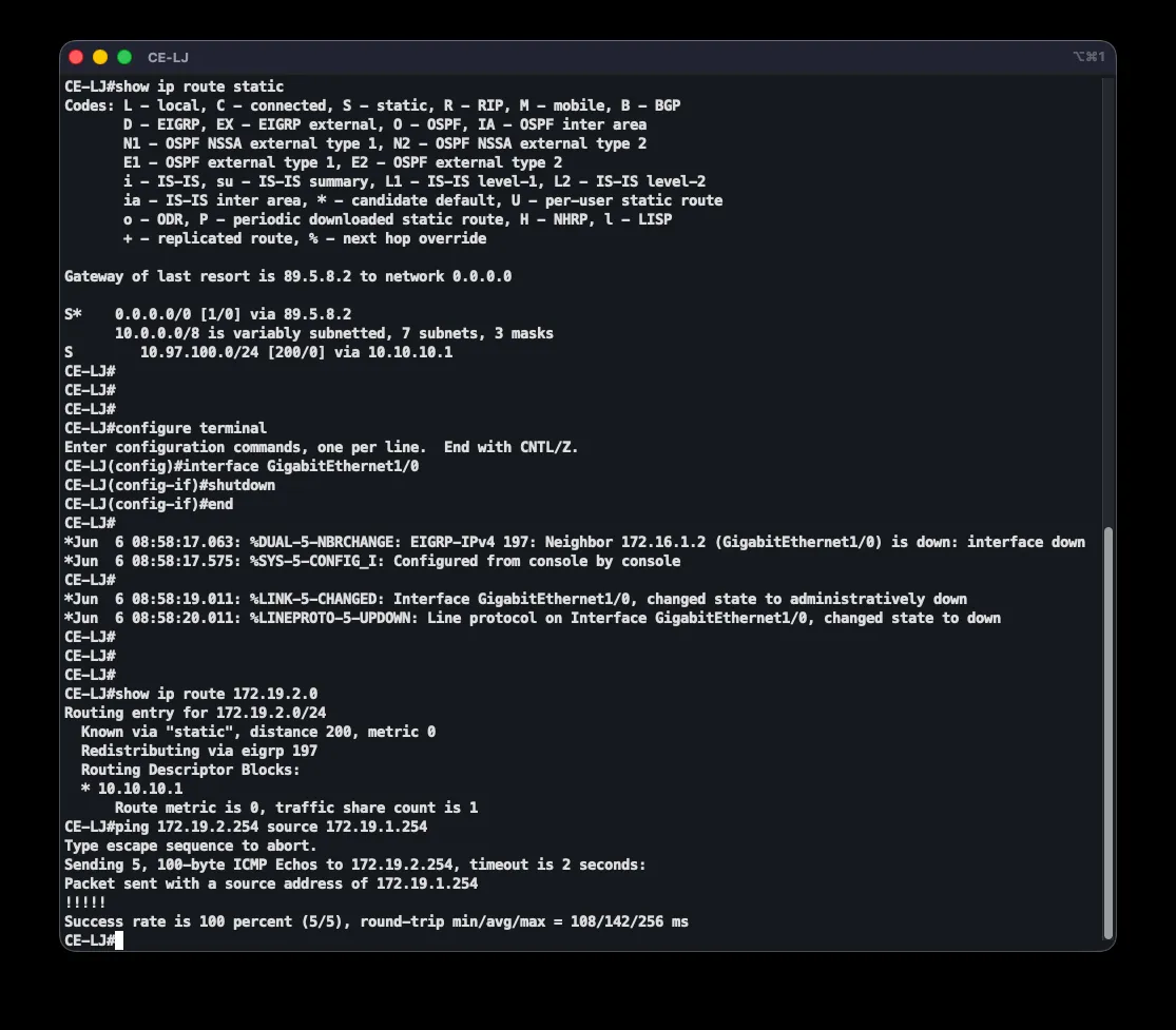
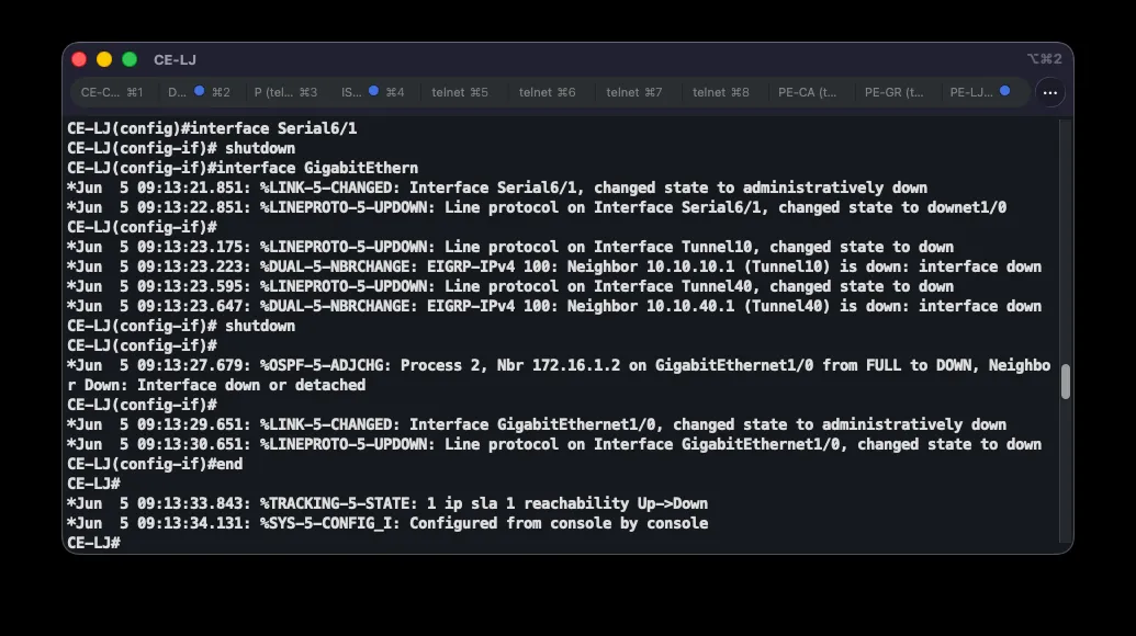
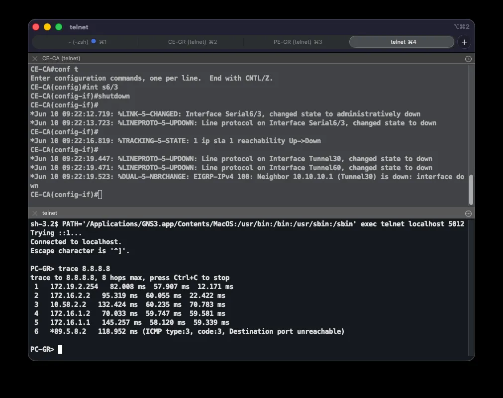
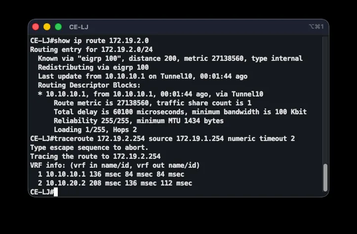
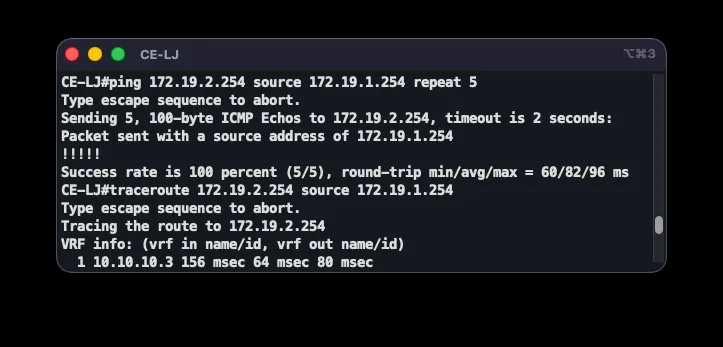
The mechanism was verified by testing: in the normal state, show ip route 172.19.2.0 shows an EIGRP route at AD 90 via PE-LJ, with traceroute revealing MPLS labels through P. After shutting down the MPLS-facing interface (shutdown on GigabitEthernet1/0), the EIGRP neighbor is lost and the route shifts to the AD-200 floating static route through the GRE tunnel — with all five test pings succeeding through the tunnel. Bringing the interface back up (no shutdown) restores EIGRP and the route returns to the primary path.
Data Center Internet Redundancy: HSRP + IP SLA
The data center has two routers (DC1 and DC2), each with its own internet link. To give devices on the DC LAN (10.97.100.0/24) resilient internet access, both routers run HSRP with a shared virtual IP, 10.97.100.254, used as the default gateway. DC1 is the primary (active) gateway; DC2 automatically takes over if DC1 loses its internet link. Link state is monitored via IP SLA.
DC1 configuration:
interface GigabitEthernet1/0 ip nat insideinterface FastEthernet0/0 ip nat outsideip nat inside source list 10 interface FastEthernet0/0 overloadaccess-list 10 permit 10.97.100.0 0.0.0.255!ip sla 1 icmp-echo 89.5.8.14 frequency 5ip sla schedule 1 life forever start-time nowtrack 1 ip sla 1 reachability!interface GigabitEthernet1/0 standby 1 ip 10.97.100.254 standby 1 priority 110 standby 1 preempt standby 1 track 1 decrement 20DC2 mirrors this with a lower starting priority (100) and IP SLA tracking its own ISP link:
interface GigabitEthernet1/0 ip nat insideinterface FastEthernet5/0 ip nat outsideip nat inside source list 10 interface FastEthernet5/0 overloadaccess-list 10 permit 10.97.100.0 0.0.0.255ip sla 2 icmp-echo 89.5.8.18 frequency 5ip sla schedule 2 life forever start-time nowtrack 2 ip sla 2 reachabilityinterface GigabitEthernet1/0 standby 1 ip 10.97.100.254 standby 1 priority 100 standby 1 preempt standby 1 track 2 decrement 20The virtual IP (standby 1 ip 10.97.100.254) is shared between both routers and provides a stable default gateway — when the active router changes, the address doesn’t, so LAN devices need no reconfiguration. DC1’s higher priority (110 vs. 100) makes it active under normal conditions, and preempt ensures the higher-priority router reclaims the active role once it recovers. The crux of the mechanism is standby 1 track 1 decrement 20: if the tracked object goes down because the ISP link becomes unreachable, DC1’s priority drops by 20 (110 → 90), falling below DC2’s 100, and DC2 takes over as active.
IP SLA actively probes ISP reachability with ICMP every five seconds — more reliable than tracking interface state alone, since an interface can stay physically up even when the ISP beyond it is unreachable. The tracked object goes “Down” when probes stop getting replies, and HSRP reacts to that state.
In normal operation DC1 is active and carries all traffic. When DC1’s ISP link fails, IP SLA detects the timeout, the tracked object goes down, DC1’s priority drops to 90, and DC2 (100) becomes active. Once DC1’s ISP link recovers, its priority returns to 110 and, thanks to preempt, it reclaims the active role.
A special case is both ISP links failing simultaneously. DC2 also decrements its own priority (100 → 80) due to its tracking, while DC1 sits at 90 — so DC1 becomes active again and keeps the virtual address. This is intentional: only DC1 has the backup link to the branches (covered next), so the virtual address must remain there to preserve a return path for DC-to-branch traffic. The decrement values were chosen so the correct router wins in every combination: both links up → DC1 (110); only DC1 down → DC2 (100 vs. 90); only DC2 down → DC1 (110 vs. 80); both down → DC1 (90 vs. 80).
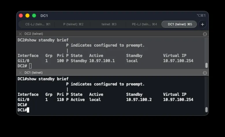
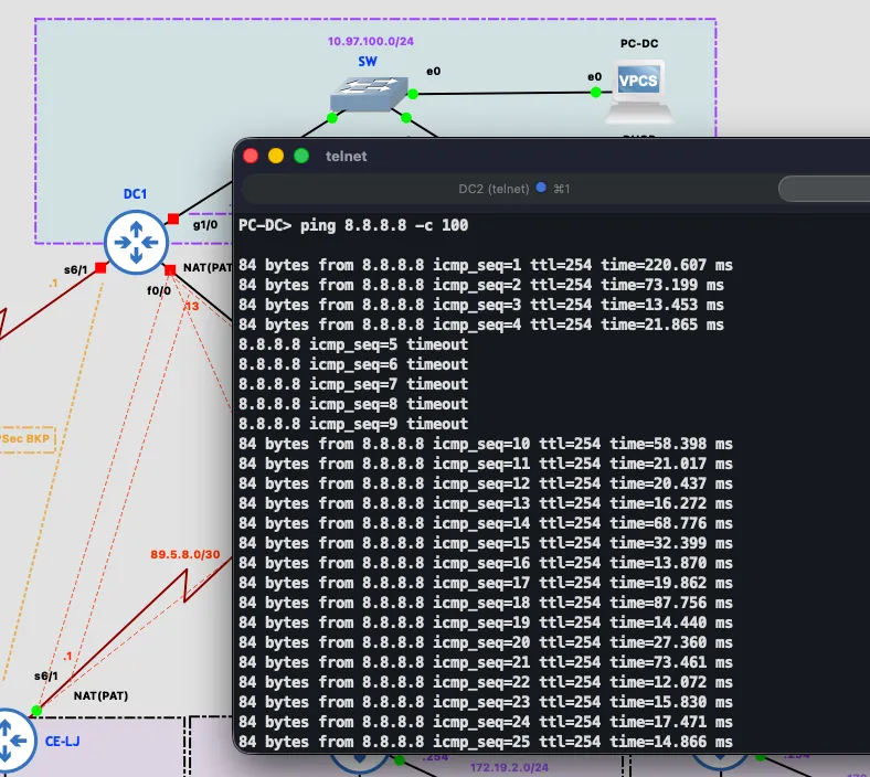
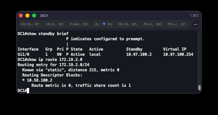
Beyond an ISP link failure, a complete failure of the DC1 device itself was tested separately, since the requirement covers both cases. These are two different detection mechanisms: an ISP link failure is caught by IP SLA (DC1 stays in the HSRP group but at reduced priority), while a complete device failure is detected by HSRP itself through missing hello messages — after the hold timer expires (10 seconds with default HSRP timers), DC2 takes over the active role and the virtual address. The test fully powered off the DC1 virtual machine in GNS3 while continuously pinging 8.8.8.8 from the DC LAN: five packets were lost during HSRP convergence, after which traffic continued flowing through DC2 with no manual intervention. show standby brief on DC2 showed state Active with an unknown standby peer, confirming DC2 was the sole remaining gateway. Powering DC1 back on, it automatically reclaimed the active role via preempt once HSRP came back up, and DC2 returned to standby.
Branch Internet Failover
When a branch loses its direct ISP link, internet traffic is automatically rerouted. The mechanism has three tiers: the direct ISP link as the primary path, a route through the MPLS core to a predefined backup branch as the first fallback, and — for CE-LJ only — a route through the dedicated backup link and the data center as the last resort.
On the CE routers (example: CE-GR), the default route is tied to IP SLA tracking, and propagation of the default route through MPLS happens via redistribution into EIGRP:
ip sla 1 icmp-echo 89.5.8.6 frequency 5ip sla schedule 1 life forever start-time nowtrack 1 ip sla 1 reachabilityip route 0.0.0.0 0.0.0.0 89.5.8.6 track 1
ip prefix-list DEFAULT-ONLY seq 5 permit 0.0.0.0/0route-map REDISTRIBUTE-DEFAULT permit 10 match ip address prefix-list DEFAULT-ONLYrouter eigrp 197 redistribute static route-map REDISTRIBUTE-DEFAULTThe default route to the ISP is tied to a tracked object (ip route ... track 1), so it’s withdrawn from the routing table as soon as the ISP becomes unreachable — avoiding a routing black hole. Redistributing via a route-map and the DEFAULT-ONLY prefix list ensures only 0.0.0.0/0 is injected into EIGRP, not the other static routes (such as the GRE-failover floating routes). Each branch thus advertises its own default route through MPLS, and the others learn it as an EIGRP external route at AD 170. While a branch has a working ISP link, its local static route (AD 1) wins; once the ISP fails and that route disappears, the EIGRP default route through MPLS from another branch takes over.
For one branch’s traffic to exit through another branch’s NAT, the PE routers add default-information originate, and the NAT access lists on the CE routers are extended to cover the other branches’ subnets:
router bgp 508 address-family ipv4 vrf ASI-VPN redistribute eigrp 197 default-information originateaccess-list 1 permit 172.19.1.0 0.0.0.255access-list 1 permit 172.19.2.0 0.0.0.255access-list 1 permit 172.19.3.0 0.0.0.255access-list 1 permit 10.97.100.0 0.0.0.255interface GigabitEthernet1/0 ip nat insideBGP doesn’t propagate a default route by default, so default-information originate explicitly enables that, letting the default route cross the MPLS core. Marking the PE-facing link as a NAT inside interface lets traffic arriving via MPLS from another branch be translated, and the extended access list ensures NAT recognizes those subnets too.
The requirements call for deterministic backup relationships — for every site, it must be predefined which other site it exits through if its own ISP link fails. Simple default-route redistribution doesn’t guarantee this: the route reflector, faced with several equally-attractive default routes, picks one “best” route by its own BGP criteria (typically lowest router-id) and reflects only that one — making the backup choice an accident of topology rather than a design decision. Backup relationships were therefore explicitly defined in a circular scheme:
| Site | Backup site | Community (own / backup) |
|---|---|---|
| Ljubuški (CE-LJ) | Grude (CE-GR) | 508:10 / 508:20 |
| Grude (CE-GR) | Čapljina (CE-CA) | 508:20 / 508:30 |
| Čapljina (CE-CA) | Ljubuški (CE-LJ) | 508:30 / 508:10 |
Determinism is achieved in two steps. First, each PE router gets a unique Route Distinguisher (PE-LJ 508:1, PE-GR 508:2, PE-CA 508:3) while keeping a common Route Target 508:1 everywhere. This turns the three default routes into three distinct VPNv4 prefixes, so the route reflector reflects all of them instead of choosing one — a standard “unique RD per PE” technique for multi-homed VPN sites. Second, each PE tags its own default route with a standard BGP community identifying its site (508:10 Ljubuški, 508:20 Grude, 508:30 Čapljina — branch number times 10), and an inbound route-map on the VPNv4 session raises BGP local-preference from the default 100 to 200, but only for the default route carrying the community of that site’s designated backup. Matching directly on BGP next-hop in an inbound route-map wasn’t possible — the IOS used reports “nexthop match not supported” — so community-based tagging was used instead, which is also more readable. Since standard communities aren’t propagated by default, send-community both is added on the route reflector and PE routers.
Configuration on PE-LJ (own tag 508:10; Ljubuški’s backup is Grude, so community 508:20 is preferred):
ip vrf ASI-VPN rd 508:1!ip prefix-list DEFAULT-ONLY seq 5 permit 0.0.0.0/0!route-map TAG-DEFAULT permit 10 match ip address prefix-list DEFAULT-ONLY set community 508:10route-map TAG-DEFAULT permit 20!ip community-list standard BACKUP-SITE permit 508:20!route-map BACKUP-INTERNET permit 10 match ip address prefix-list DEFAULT-ONLY match community BACKUP-SITE set local-preference 200route-map BACKUP-INTERNET permit 20!router bgp 508 address-family ipv4 vrf ASI-VPN redistribute ospf 2 match internal external 1 external 2 route-map TAG-DEFAULT default-information originate address-family vpnv4 neighbor 10.5.8.9 send-community both neighbor 10.5.8.9 route-map BACKUP-INTERNET inThe TAG-DEFAULT route-map tags only the default route on redistribution (first clause); everything else passes through untagged (second clause). The inbound BACKUP-INTERNET route-map raises local-preference only at the intersection of two conditions — prefix 0.0.0.0/0 carrying the designated backup site’s community — and passes everything else unchanged. One subtlety: a locally generated default route carries Cisco weight 32768, which is evaluated before local-preference in BGP best-path selection. So while a branch has its own ISP link, its traffic exits locally without detour. Only once a CE withdraws its own default route (due to IP SLA) does the local candidate disappear, and local-preference 200 deterministically selects the designated backup site. The mechanism degrades gracefully: if the backup site also loses internet, the third site’s route at local-preference 100 remains, keeping the network functional. On PE-GR, the BACKUP-SITE community list permits 508:30 (Čapljina), and on PE-CA, 508:10 (Ljubuški), with the matching own-tag in TAG-DEFAULT. Since the whole mechanism operates at the BGP VPNv4 layer, it’s independent of the PE-CE routing protocol and survives the EIGRP-to-OSPF migration unchanged (see below).
Note
Changing the Route Distinguisher flushes the VRF table — on the IOS version used, it requires deleting and recreating the VRF — so this was rolled out as a planned, one-PE-at-a-time change, verifying convergence before moving to the next router.
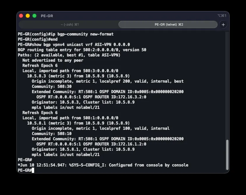
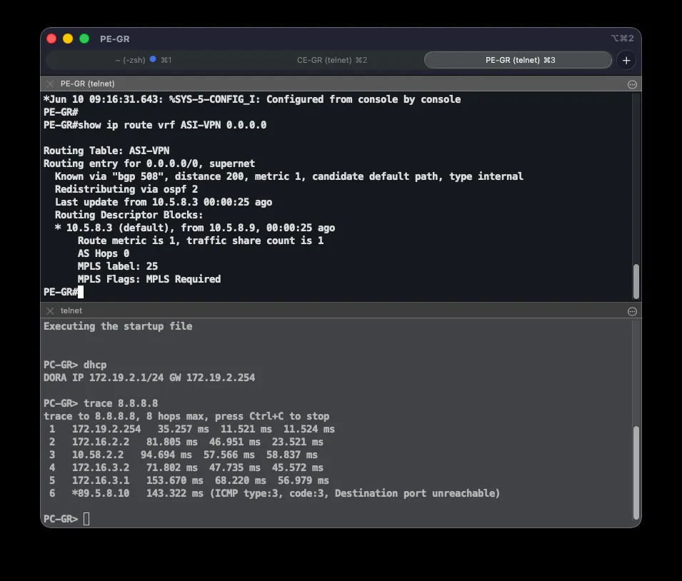
Correctness is verified with show bgp vpnv4 unicast vrf ASI-VPN 0.0.0.0, which on each PE shows all three default-route candidates: the locally generated one (weight 32768, best under normal conditions) and two reflected routes, with the one carrying the designated backup site’s community at local-preference 200. ip bgp-community new-format makes communities display as 508:X instead of raw decimals. After shutting down CE-GR’s ISP link, Grude’s traffic exited via NAT on CE-CA — confirmed by next-hop 10.5.8.3 in show ip route vrf ASI-VPN 0.0.0.0 on PE-GR and a traceroute to 8.8.8.8 from a client — exactly per the defined mapping, not an arbitrary site. Additionally shutting down CE-CA’s ISP link shifted traffic to the last remaining site (Ljubuški), confirming graceful degradation.
Backup Path to the Data Center
For the extreme case where CE-LJ loses both its ISP and MPLS links, internet traffic exits through a backup link to the data center. This backup connection is an S2S GRE+IPsec tunnel (Tunnel100) between CE-LJ and DC1, physically routed over dedicated serial links through the BKP router. The tunnel doesn’t depend on the internet, so it stays up even if ISP access fails on either end — the BKP router only relays the encapsulated (GRE/ESP) traffic between the tunnel endpoints:
crypto ipsec profile ASI-IPSEC-BKP set transform-set ASI-TS
interface Tunnel100 ip address 10.58.100.2 255.255.255.252 tunnel source Serial6/2 tunnel destination 10.58.10.1 tunnel protection ipsec profile ASI-IPSEC-BKPip route 10.58.10.0 255.255.255.252 10.58.10.5ip route 0.0.0.0 0.0.0.0 10.58.100.1 210
interface Tunnel100 ip address 10.58.100.1 255.255.255.252 ip nat inside tunnel source Serial6/1 tunnel destination 10.58.10.6 tunnel protection ipsec profile ASI-IPSEC-BKPip route 10.58.10.4 255.255.255.252 10.58.10.2ip route 172.19.1.0 255.255.255.0 10.58.100.2 215A separate IPsec profile (ASI-IPSEC-BKP) is used deliberately: the main ASI-IPSEC profile on the DMVPN tunnels uses shared protection tied to the internet-facing interface, which can’t be shared with a tunnel sourced from a different interface (the serial link to BKP). Since this tunnel is point-to-point (tunnel destination is set), shared isn’t needed. The underlay route ip route 10.58.10.0/30 ... 10.58.10.5 is critical — without it, the tunnel destination (10.58.10.1) would resolve via the default route, which points back into the tunnel itself, creating a recursive loop. On CE-LJ, the floating default route (AD 210) now routes internet traffic into the encrypted tunnel instead of the bare serial link; traffic exits to the internet only after NAT on DC1, which marks the backup tunnel as a NAT inside interface. This route only takes over once neither the direct ISP (AD 1) nor the EIGRP default route through MPLS (AD 170) is available.
When both DC1’s and DC2’s ISP links fail simultaneously, both branches’ encrypted tunnels to the data center go down, and the branches would normally lose reachability to the DC LAN (10.97.100.0/24). All three branches keep talking to the data center in this case too, routed through CE-LJ’s Tunnel100. For CE-GR and CE-CA to use that path, CE-LJ conditionally advertises the DC LAN into the MPLS core:
ip route 10.97.100.0 255.255.255.0 10.58.100.1 215ip prefix-list DC-LAN seq 5 permit 10.97.100.0/24route-map REDIST-DC-BKP permit 10 match ip address prefix-list DC-LANrouter eigrp 197 redistribute static route-map REDIST-DC-BKPip route 172.19.1.0 255.255.255.0 10.58.100.2 215ip route 172.19.2.0 255.255.255.0 10.58.100.2 215ip route 172.19.3.0 255.255.255.0 10.58.100.2 215This relies on the floating-static-route property: the route to the DC LAN via the backup tunnel has a high AD (215), so it’s only installed once the better, primary path to the DC disappears. Since redistribution into a routing protocol only picks up routes actually present in the table, the DC LAN is advertised into MPLS only while the primary path is down — exactly when both DC ISP links have failed. The PE routers redistribute that route into BGP VPNv4, so CE-GR and CE-CA receive it through MPLS and send DC-bound traffic to CE-LJ, which forwards it through the encrypted backup tunnel to DC1; return routes on DC1 (also AD 215) send traffic back the same way. As soon as the DC’s internet recovers and the primary path returns, the floating route disappears, redistribution stops, and the branches automatically fall back to their direct tunnels — no manual intervention needed. This avoids permanently routing all DC traffic through a bottleneck backup link, while keeping the backup connection limited to static routes with no dynamic protocol of its own. In the base configuration, redistribution targets EIGRP 197 as the PE-CE protocol; after the first migration (below), the same condition maps to redistribute static ... router ospf 2.
Verified on the full topology: shutting down both DC ISP links brought down both branches’ tunnels to the DC, CE-LJ’s floating route to the DC LAN activated and was redistributed into MPLS, and both CE-GR and CE-CA reached the DC LAN through the backup tunnel (5/5 pings each from their LAN addresses), with traffic through Tunnel100 confirmed encrypted. Restoring the DC ISP links automatically returned the branches to their direct tunnels.
Network Migrations
Three migrations progressively modernize the architecture without interrupting service. Each follows the same template: analysis of the starting state, the target state, an exact operational sequence, a risk and rollback assessment, and an execution report covering the affected part of the topology, outage duration, and stability confirmation.
All three were performed against the live, already-configured network using a ship-in-the-night approach — the new protocol or encapsulation runs in parallel with the old one, is verified while the old configuration still carries traffic, and only then is the cutover performed while measuring packet loss. Before each migration, a GNS3 project export was taken as a safety net.
Migration 1: EIGRP to OSPF on the PE-CE Segment
Starting state. The PE-CE segment within VRF ASI-VPN runs EIGRP (AS 197). EIGRP routes are redistributed into MP-BGP across the MPLS core, and the internet default route is propagated via redistribution of a static route. All inter-branch communication and the MPLS-based internet failover depend on EIGRP working correctly across the three PE-CE pairs.
Target state. EIGRP on the PE-CE segment is replaced by OSPF (process 2), with redistribution into MP-BGP preserved. Branch routes should appear as OSPF inter-area routes (O IA, AD 110), the EIGRP neighbor table must be empty everywhere, and MPLS-based internet failover must keep working unchanged.
Steps:
- Configure OSPF in parallel with EIGRP on all CE routers (
router ospf 2) and PE routers (router ospf 2 vrf ASI-VPN); EIGRP keeps carrying traffic. - Verify full adjacency with
show ip ospf neighbor— all three PE-CE pairs must show FULL. - Add OSPF redistribution into MP-BGP alongside the existing EIGRP redistribution (both sources temporarily coexist).
- Cutover: remove EIGRP — the BGP redistribution and the
router eigrp 197process on CE and PE routers — while continuously measuring packet loss. - Clean up leftovers and save configuration.
router ospf 2 router-id 172.16.1.1 network 172.16.1.0 0.0.0.3 area 0 network 172.19.1.0 0.0.0.255 area 0 default-information originate
router ospf 2 vrf ASI-VPN router-id 172.16.1.2 network 172.16.1.0 0.0.0.3 area 0 redistribute bgp 508 subnets default-information originate
router bgp 508 address-family ipv4 vrf ASI-VPN redistribute ospf 2 match internal external 1 external 2 default-information originateThe key difference from EIGRP is default route propagation. Under EIGRP, 0.0.0.0/0 propagated via redistribution of a static route; OSPF doesn’t pick up a default route from static redistribution and instead requires an explicit default-information originate — on both sides: the CE router (to inject its local internet exit into OSPF) and the PE router within the VRF (to pass the default route from the core to the branch).
Risk and rollback. The main risk was a routing black hole during cutover if EIGRP were removed before OSPF reached full adjacency — mitigated by running both protocols in parallel and explicitly verifying FULL state first. A second risk was losing the default route entirely, since OSPF doesn’t inherit it from static redistribution the way EIGRP does; missing default-information originate on either side would break MPLS-based internet failover (symptom: 0.0.0.0/0 disappearing from the BGP VPNv4 table). This was mitigated by adding the command on both sides and testing failover before and after. A third risk — exceeding the two-packet loss budget — was mitigated by keeping the cutover short, after OSPF convergence was confirmed.
Two rollback layers were available: a quick live rollback (re-adding EIGRP redistribution and removing the OSPF config, possible since EIGRP stayed active until cutover) and a full rollback by restoring the SIP-backup-pred-migraciju-1b.gns3project snapshot taken immediately before the migration.
Results. The affected topology was the three PE-CE pairs and their branches. Outage was measured with a continuous ping from PC-LJ to another branch’s subnet during cutover: just one packet lost out of fifty, within the two-packet budget. Stability was confirmed across multiple checks: all three PE-CE pairs showed stable full adjacency, the EIGRP neighbor table was empty everywhere, branch routes appeared as O IA, and both internet failover and end-to-end connectivity were re-verified. Cleanup removed the now-empty router eigrp 197 process left on the PE routers and the bare static redistribution on the CE routers.
Migration 2: Static to EIGRP on the DC Tunnels
Starting state. Traffic between the branches and the data center traverses the GRE+IPsec tunnels carrying floating static routes. The statics are manually maintained, don’t detect a tunnel going down on their own (relying on the separate IP SLA mechanism on DC1), and offer no automatic redundancy between the primary (DC1) and backup (DC2) hubs beyond carefully tuned administrative distances.
Target state. The static routes on the tunnels are replaced by dynamic routing via EIGRP (AS 100) as an overlay protocol: DC1 becomes the primary hub, DC2 the backup, and the branches spokes. This also prepares the control plane for the third migration, since DMVPN uses the same overlay. The MPLS → VPN → backup failover order must remain intact: inter-branch traffic still prefers MPLS, with EIGRP over the tunnels as the backup path.
Steps:
- Configure EIGRP (AS 100) in parallel with the existing statics on hubs and spokes; statics keep carrying traffic.
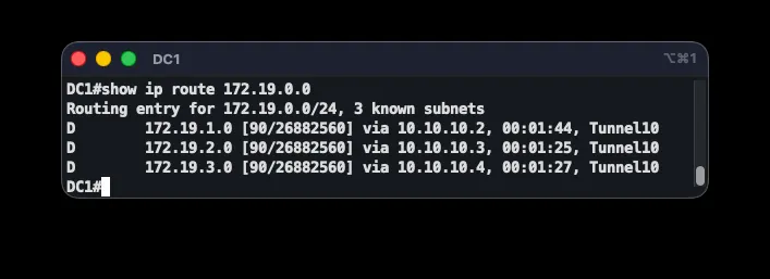
- Verify adjacency and topology with
show ip eigrp neighborsandshow ip route. - Raise EIGRP’s administrative distance on the spokes with
distance eigrp 200 210, and tunedelayto prefer DC1. - Cutover: remove the floating static routes while measuring packet loss.
- Remove the IP SLA tunnel-down workaround on DC1 (EIGRP replaces it) and save configuration.
router eigrp 100 network 10.10.10.0 0.0.0.3 network 10.10.40.0 0.0.0.3 network 172.19.1.0 0.0.0.255 passive-interface FastEthernet0/0 distance eigrp 200 210 no auto-summary
interface Tunnel10 delay 1000interface Tunnel40 delay 2000
interface Tunnel10 no ip split-horizon eigrp 100The DC subnet — which has no MPLS competitor — now uses the EIGRP route (AD 200), while other branches’ subnets still prefer MPLS (O IA, AD 110). no ip split-horizon eigrp 100 on the hub’s tunnels is required so the hub can re-advertise one spoke’s routes to the others.
Risk and rollback. The biggest risk was breaking the failover order: an internal EIGRP route has AD 90, lower than OSPF’s 110, so by default EIGRP would have taken over inter-branch traffic from MPLS. This was eliminated by raising the spoke-side distance with distance eigrp 200 210. A second risk was breaking inter-branch communication by disabling next-hop-self on classic point-to-point GRE tunnels — the hub would advertise one branch’s route with the other branch’s tunnel address as next-hop, which is unreachable from a different tunnel subnet. This was avoided by leaving next-hop-self at its default and deferring that change to the third migration (mGRE). A third risk — picking the wrong hub or routing loops — was mitigated with delay tuning and no ip split-horizon.
Quick rollback: the static routes stayed in place until cutover, so re-adding them and removing the EIGRP process restores the previous state without an outage. Full rollback: restore the SIP-backup-pred-migraciju-2.gns3project snapshot (post-Migration-1 state).
Results. The affected topology was the tunnels between branches and the data center. There was practically no outage — cutover lost zero packets out of sixty, since the EIGRP route already had the same next-hop toward DC1 as the static route it replaced. Two resilience tests followed. First, the MPLS link was shut down to verify inter-branch traffic shifting to the overlay — convergence (~30 seconds) turned out to depend on the prefix being withdrawn from the BGP VPNv4 table rather than on EIGRP itself, since a branch temporarily retains its old MPLS route to the now-down neighbor. Second, the tunnel to DC1 was shut down: DC traffic shifted to DC2 with zero packet loss (45/45), and reverted to DC1 once the tunnel recovered, thanks to its better metric.
Migration 3: P2P IPsec to DMVPN Dual-Hub Phase 3
Starting state. Six separate P2P GRE+IPsec tunnels connect the branches to the data center — each branch has a dedicated, statically-destined tunnel to DC1 and to DC2. This design doesn’t exchange traffic directly between branches (everything transits a hub) and scales poorly, since every new site pair requires a manually-defined tunnel. The EIGRP overlay introduced in the previous migration already runs over these tunnels.
Target state. The six P2P tunnels are replaced by DMVPN Dual-Hub Dual-Cloud Phase 3: multipoint GRE (mGRE) with NHRP, where DC1 and DC2 each become the Next Hop Server (NHS) for one cloud, and branches register dynamically. The goal includes direct inter-branch communication (DMVPN’s third phase) without transiting a hub, preserved encryption, and an unchanged failover order. The addressing plan and EIGRP overlay stay the same — fundamentally this is a pure encapsulation swap.
Steps. The migration was performed with a purpose-built automation script (migracija_3b.py) that sends configuration commands to device consoles through GNS3:
- Phase 1 — convert the backup cloud (DC2 as hub) while the primary cloud (DC1) and MPLS remain untouched. The hub is configured first, then the spokes.
- Verify cloud 2: NHRP spoke registration, EIGRP adjacency, and encrypted traffic.
- Phase 2 — convert the primary cloud (DC1 as hub), with the now-converted backup cloud as a safety net.
- Verify cloud 1.
- Verify Phase 3 (direct inter-branch tunnels) and save configuration on all devices.
Hub side (DC1, Tunnel10):
interface Tunnel10 ip address 10.10.10.1 255.255.255.0 ip nhrp authentication ASI-NHRP ip nhrp map multicast dynamic ip nhrp network-id 1 ip nhrp redirect no ip split-horizon eigrp 100 no ip next-hop-self eigrp 100 no tunnel destination tunnel mode gre multipoint tunnel key 1Spoke side (CE-LJ, Tunnel10):
interface Tunnel10 ip address 10.10.10.2 255.255.255.0 ip nhrp authentication ASI-NHRP ip nhrp network-id 1 ip nhrp map 10.10.10.1 89.5.8.13 ip nhrp map multicast 89.5.8.13 ip nhrp nhs 10.10.10.1 ip nhrp shortcut delay 1000 no tunnel destination tunnel mode gre multipoint tunnel key 1 tunnel protection ipsec profile ASI-IPSEC sharedUnlike the previous migration, next-hop-self is now disabled on the hubs. With mGRE and NHRP this no longer breaks inter-branch communication — instead it’s exactly what enables DMVPN’s third phase: a spoke’s routing table shows the other spoke’s real tunnel address as next-hop, so on receiving an NHRP redirect from the hub it can build a direct tunnel to that spoke.
Risk and rollback. The most serious risk was simultaneously losing connectivity to the data center if the conversion went wrong on both clouds at once — mitigated by converting cloud-by-cloud, starting with the backup cloud, so at least one cloud plus MPLS stays operational at all times. A second risk was a gap in encryption: since both tunnels on a spoke now share the same source interface, IPsec protection must be marked shared, but adding that flag on top of existing crypto state isn’t accepted, which would leave the hub receiving unencrypted traffic. This was resolved with a careful ordering — removing protection from both tunnels first (resetting ISAKMP), then re-adding it with shared — automated by the script. A third risk was crashing the router emulation in the simulator: deleting a tunnel interface that has crypto and NHRP configuration (no interface Tunnel) crashes the GNS3 7200-series emulation, so unused source tunnels on the hubs are administratively shut down rather than deleted.
Because the migration proceeded cloud-by-cloud, a failure on one cloud left the other cloud and MPLS untouched as a working path, allowing rollback of just the affected cloud. Full rollback: restore the SIP-backup-pred-migraciju-3.gns3project snapshot (post-Migration-2 state). A snapshot of the final state was also taken after successful verification.
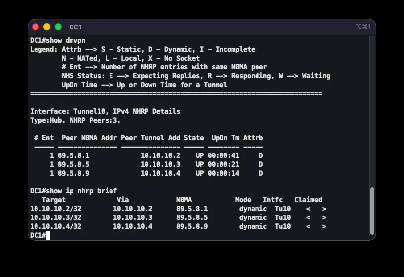
Results. The affected topology was the tunnels between the branches and both hubs; during each cloud’s conversion, the outage was confined to that cloud while the other cloud (and MPLS) carried traffic — so no real service interruption occurred. Stability was confirmed diagnostically: both hubs showed three registered NHRP spokes in state UP, EIGRP adjacencies were complete, and on the spoke side two active ISAKMP associations (to DC1 and DC2) showed growing encrypt/decrypt counters, confirming encrypted transport through both clouds. The failover order remained intact — inter-branch traffic still prefers MPLS (O IA, AD 110).
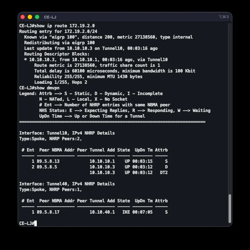
DMVPN’s third phase — direct inter-branch communication — was specifically verified. Temporarily shutting down the MPLS interface on CE-LJ shifted traffic to the overlay, with the route showing the other spoke’s real tunnel address as next-hop. The first batch of pings was lost during NHRP resolution and IPsec association setup for the new direct tunnel, while a second batch passed completely (20/20). show dmvpn confirmed a direct dynamic tunnel between CE-LJ and CE-GR, with traffic flowing spoke-to-spoke instead of through a hub. Restoring the MPLS interface returned the route to MPLS, confirming the strict failover order remained functional.
Conclusion
This project designed and implemented a complete network infrastructure for ASI ltd. in GNS3, spanning everything from basic connectivity and internet access to advanced routing, encryption, and failure resilience. All requirements were met: automatic address assignment via DHCP, internet access via NAT, MPLS L3 VPN as the primary inter-branch path, GRE tunnels protected by IPsec, internet redundancy at the data center via HSRP and IP SLA, and a multi-tier failover mechanism. Every segment’s functionality was confirmed with diagnostic commands and connectivity tests, and its resilience with targeted simulations of link and segment failures.
The central design decision running through the whole project is the strict failover order — MPLS first, VPN tunnels second, backup link last — preserved through every later change. This constraint drove a number of technical choices, most notably the administrative-distance tuning needed when introducing EIGRP as an overlay protocol, so dynamic routing over the tunnels would never preempt the primary MPLS path.
The three migrations showed that a live, already-configured network can be modernized with negligible disruption using a ship-in-the-night approach combined with loss measurement during cutover. The EIGRP-to-OSPF migration cost just one lost packet; the static-to-dynamic migration on the DC tunnels lost none; and the move to DMVPN Dual-Hub Phase 3 proved direct inter-branch communication. Throughout, seemingly small details turned out to be decisive: explicitly generating the default route when changing protocols, the correct ordering when applying shared IPsec protection to tunnels sharing a source, and awareness of the simulator’s own limitations. The final migration was further automated with a dedicated script, reducing the chance of manual configuration errors and speeding up repeated runs.